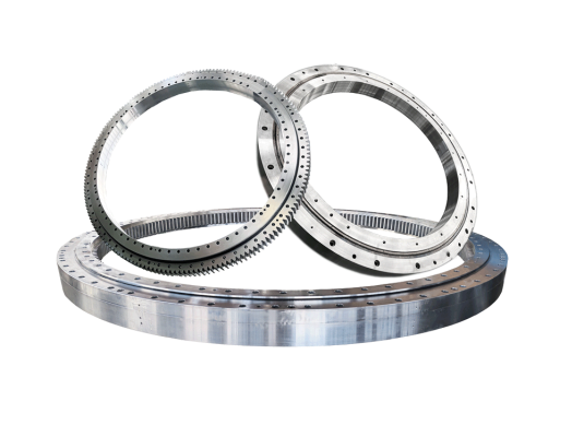
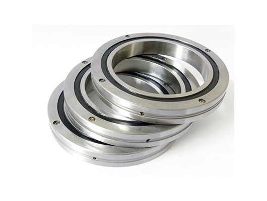
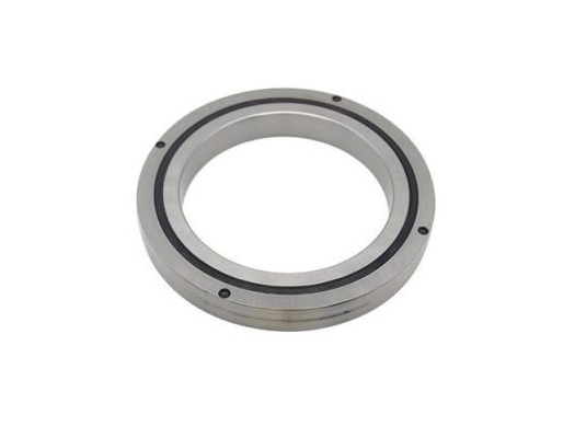
A cross roller slewing bearing is two seat rings, one raceway, and a single row of cylindrical rollers set at 90° to each other in…
A cross roller slewing bearing is two seat rings, one raceway, and a single row of cylindrical rollers set at 90° to each other in strict 1:1 alternation. Because each roller contacts the 90° V-groove at 45°, the same bearing carries axial force, radial force and overturning moment simultaneously — no second row, no separate thrust washer, no additional bearing position.
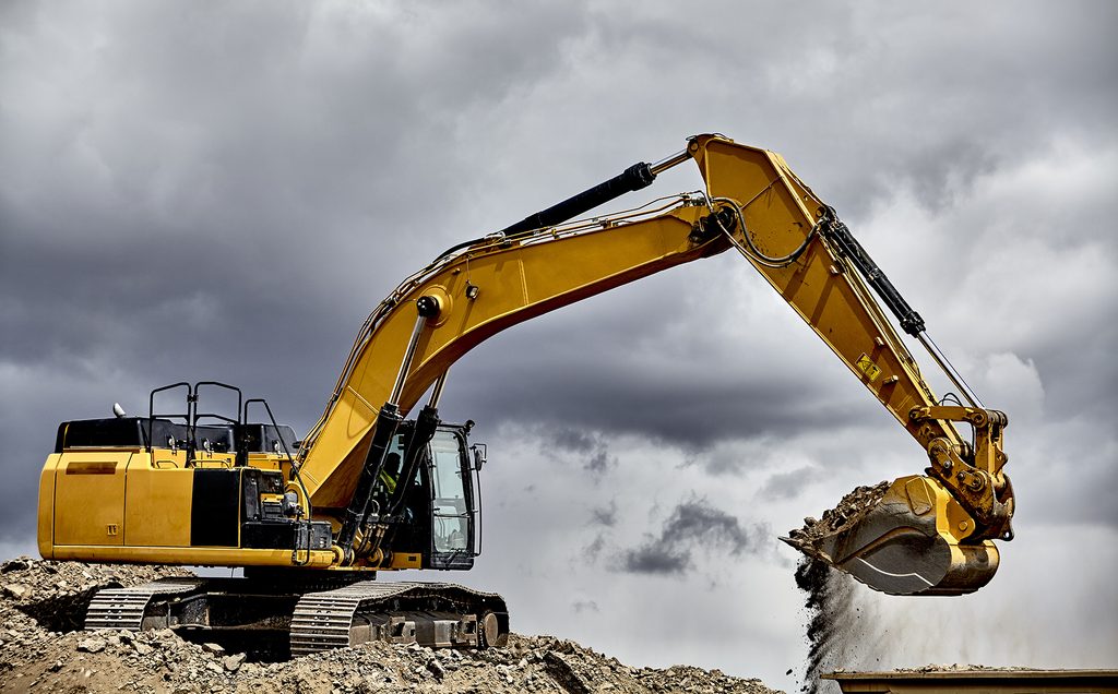
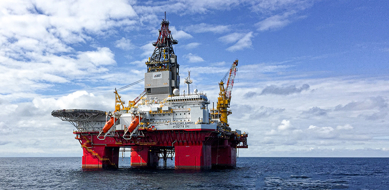
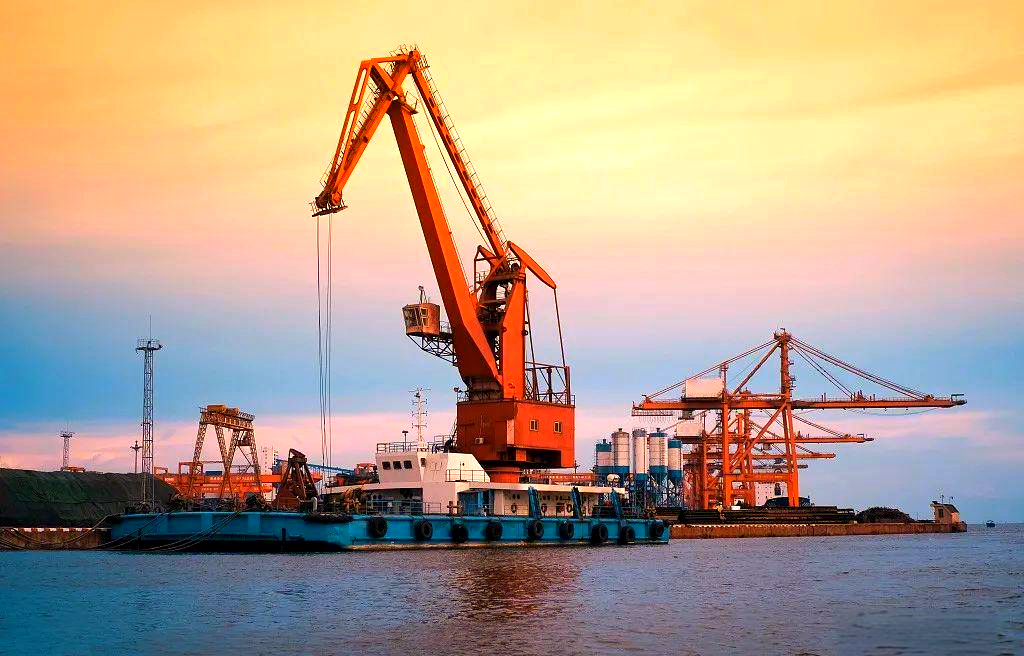
That single-raceway geometry is why the type is chosen wherever the structure has to stay stiff and the rotation has to stay accurate: stacker-reclaimers, deck cranes, mining equipment, aerial platforms, positioners and machine tools. It is also why it demands more from the mounting interface than a ball type does — a point this page addresses directly, because most field problems with cross roller bearings originate at the bolted joint, not in the raceway.
| Element | Description |
|---|---|
| Rings | Two seat rings, split at the raceway centre plane; not separable after assembly |
| Rolling element | Cylindrical rollers, hardened and ground, arranged 1:1 at 90° |
| Contact | Line contact at 45° contact angle on a single 90° V-groove |
| Load capacity | Axial, radial and tilting moment simultaneously |
| Retention | Spacers or a segmented cage keep roller spacing and prevent skew |
Because the rollers are in line contact rather than point contact, the elastic deformation under load is small and the load is spread over a long raceway length. The practical consequences:
| Cross roller | Four-point contact ball | Three-row roller | |
|---|---|---|---|
| Contact type | Line, 45° | Point, 45° (or 35°/45° pairs) | Line, dedicated rows |
| Tilting stiffness | High | Medium | High |
| Axial capacity | High | High | Very high |
| Radial capacity | High | Low to medium | High |
| Axial height | Lowest | Low | Highest |
| Friction torque | Medium | Low | High |
| Raceway clearance | Can be set near zero, even preloaded | Small clearance typical | Clearance per row |
| Sensitivity to mounting flatness | High | Medium | Medium |
| Best fit | Crane slews, positioners, mining, machine tools, platforms | General rotation, wind pitch/yaw, light structures | Heavy vertical loads, large excavators, ladle turrets |
Rule of thumb: if the structure deflects visibly under load and the customer is fighting it, specify cross roller. If the load is dominated by axial force with a light structure, a four-point contact ball will be cheaper and more forgiving.
A cross roller bearing has a single raceway shared by both rings. Any distortion of the mounting flange is transmitted directly into that raceway as a clearance variation, an edge load, or a localised overload. Three items decide the outcome:
1. Mounting surface flatness. The flange must be machined, not flame-cut and shimmed. Flatness is normally specified per unit diameter (for example 0.1 mm over the full bolted circle for mid-size units); the exact figure is on the drawing and should be measured, not assumed.
2. Bolt preload. Bolts are sized to keep the joint closed under the full overturning moment — the bearing must never see the moment through a gap. Use the specified torque, in the specified sequence, in at least two passes, with hardened washers. Thread engagement and bolt grade are part of the calculation, not a workshop decision.
3. Concentricity and runout check after assembly. Measure gear runout (if geared) and ring radial/axial runout with the bolts final-torqued. A bearing that turns freely on the bench and binds after bolting down is telling you the flange is not flat.
Supply the mating structure dimensions with the order and the bearing can be checked against the actual interface rather than a nominal drawing.
| Prefix | Configuration | Typical use |
|---|---|---|
| 110 | No gear, plain raceway | Direct-drive slews, positioners, idler turntables |
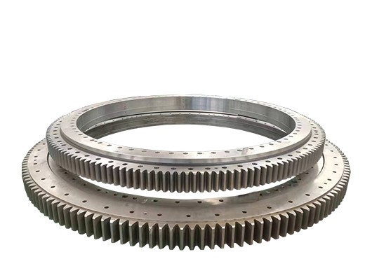
| 111 | External gear, standard tooth section | Slewing drives with pinion outside the ring |
| 112 | External gear, heavy tooth section | Higher tangential load, larger drives |
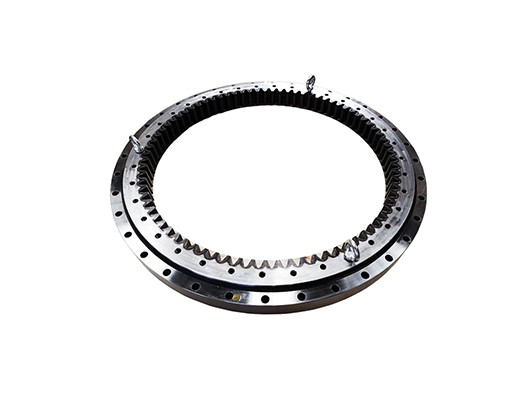
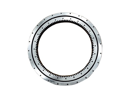
| 113 | Internal gear, standard tooth section | Compact envelopes, protected tooth mesh |
| 114 | Internal gear, heavy tooth section | High torque indexing, mining equipment |
Teeth are cut after heat treatment or hard-finished to control distortion, then inspected for profile, lead, single and cumulative pitch error, and backlash against the mating pinion drawing.
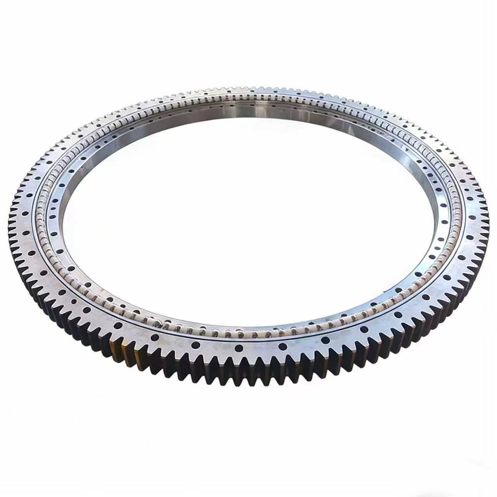
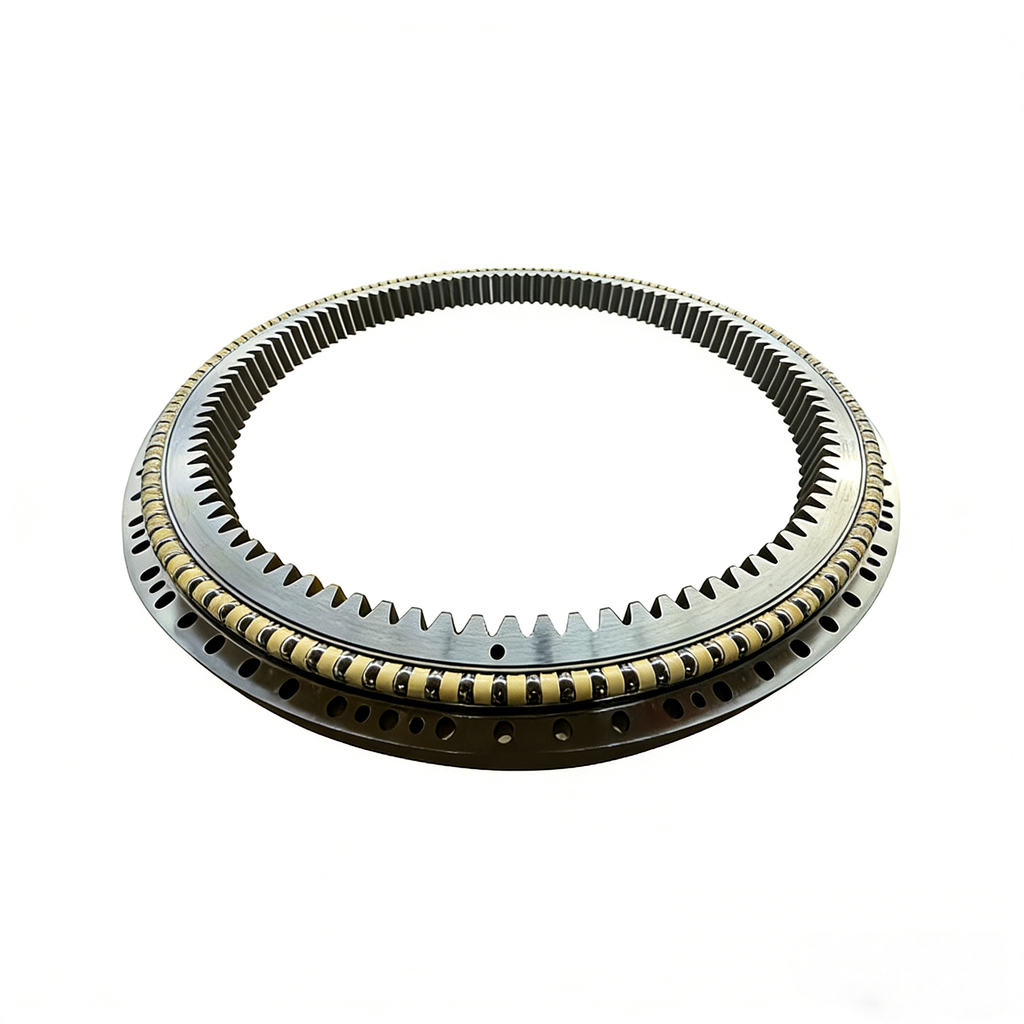
Raceway centre diameter D₀ from 500 mm to 4,500 mm. All five prefixes are available at every size listed; sizes beyond this table are built to drawing.
| D₀ (mm) | Series | 110 no gear | 111 ext. | 112 ext. heavy | 113 int. | 114 int. heavy |
|---|---|---|---|---|---|---|
| 500 | 25 | 110.25.500 | 111.25.500 | 112.25.500 | 113.25.500 | 114.25.500 |
| 560 | 25 | 110.25.560 | 111.25.560 | 112.25.560 | 113.25.560 | 114.25.560 |
| 630 | 25 | 110.25.630 | 111.25.630 | 112.25.630 | 113.25.630 | 114.25.630 |
| 710 | 25 | 110.25.710 | 111.25.710 | 112.25.710 | 113.25.710 | 114.25.710 |
| 800 | 30 | 110.30.800 | 111.30.800 | 112.30.800 | 113.30.800 | 114.30.800 |
| 900 | 30 | 110.30.900 | 111.30.900 | 112.30.900 | 113.30.900 | 114.30.900 |
| 1000 | 30 | 110.30.1000 | 111.30.1000 | 112.30.1000 | 113.30.1000 | 114.30.1000 |
| 1120 | 30 | 110.30.1120 | 111.30.1120 | 112.30.1120 | 113.30.1120 | 114.30.1120 |
| 1250 | 40 | 110.40.1250 | 111.40.1250 | 112.40.1250 | 113.40.1250 | 114.40.1250 |
| 1400 | 40 | 110.40.1400 | 111.40.1400 | 112.40.1400 | 113.40.1400 | 114.40.1400 |
| 1600 | 40 | 110.40.1600 | 111.40.1600 | 112.40.1600 | 113.40.1600 | 114.40.1600 |
| 1800 | 40 | 110.40.1800 | 111.40.1800 | 112.40.1800 | 113.40.1800 | 114.40.1800 |
| 2000 | 50 | 110.50.2000 | 111.50.2000 | 112.50.2000 | 113.50.2000 | 114.50.2000 |
| 2240 | 50 | 110.50.2240 | 111.50.2240 | 112.50.2240 | 113.50.2240 | 114.50.2240 |
| 2500 | 50 | 110.50.2500 | 111.50.2500 | 112.50.2500 | 113.50.2500 | 114.50.2500 |
| 2800 | 50 | 110.50.2800 | 111.50.2800 | 112.50.2800 | 113.50.2800 | 114.50.2800 |
| 3150 | 60 | 110.60.3150 | 111.60.3150 | 112.60.3150 | 113.60.3150 | 114.60.3150 |
| 3550 | 60 | 110.60.3550 | 111.60.3550 | 112.60.3550 | 113.60.3550 | 114.60.3550 |
| 4000 | 60 | 110.60.4000 | 111.60.4000 | 112.60.4000 | 113.60.4000 | 114.60.4000 |
| 4500 | 60 | 110.60.4500 | 111.60.4500 | 112.60.4500 | 113.60.4500 | 114.60.4500 |
Reading the designation: the three-digit prefix is the structure code (see gear table above), the middle group is the section size series — larger number, deeper section and heavier roller — and the last group is the raceway centre diameter in millimetres. A 110.40.1600 is therefore an ungeared cross roller bearing with a 1,600 mm raceway centre diameter in the 40 size series.
Final values follow the customer drawing and load case.
| Item | Range / value |
|---|---|
| Type | Single row crossed cylindrical roller slewing bearing |
| Ring material | 50Mn or 42CrMo4 forged ring, per size and load class |
| Raceway diameter D₀ | 500–4,500 mm |
| Overall diameter | Up to approx. 5,000 mm at D₀ 4,500 |
| Raceway hardness | 55–62 HRC, induction hardened |
| Core hardness | 50Mn 187–241 HB / 42CrMo 229–269 HB |
| Rollers | Hardened bearing steel, ground, matched diameter sets, with spacers or segmented cage |
| Contact angle | 45° |
| Axial / radial clearance | Set per drawing; near-zero or preloaded on request |
| Gear | None (110), external (111/112), internal (113/114) |
| Gear accuracy | Inspected to drawing, GB/T 10095 or ISO 1328 equivalent |
| Seal | Double-lip NBR, purgeable |
| Lubrication | Lithium-complex grease, or oil for high-duty-cycle applications |
| Coating | ISO 12944 C3 / C4 / C5-M on request, 240–320 µm DFT |
| Operating temperature | −30 °C to +60 °C (low-temperature steel on request) |
| Standards | Customer drawing, JB/T 2300, GB/T 10095 for gearing |
Documentation package per bearing: material certificates, heat-treatment records, hardness and case-depth report, UT and MPI reports, dimensional report, gear report, torque test record, coating report.

Send these six items and a quotation can be issued without a round of questions:
If the model is not in the table, send the drawing — non-standard diameters and gear data are routine, not exceptional.
Email: [email protected]
Mob./Whatsapp: +8613938815302
Professional Team
Moderate Prices
Quality Service
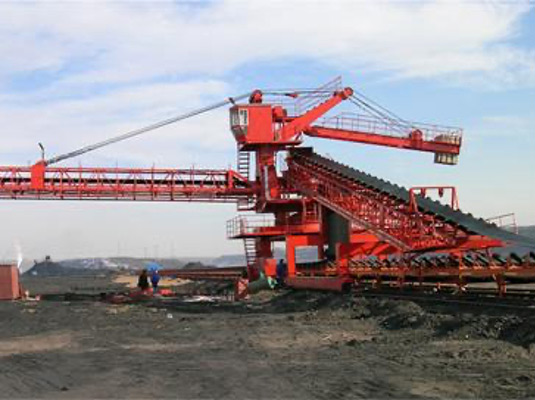
Bucket wheel stacker reclaimer
Bucket wheel stacker reclaimer
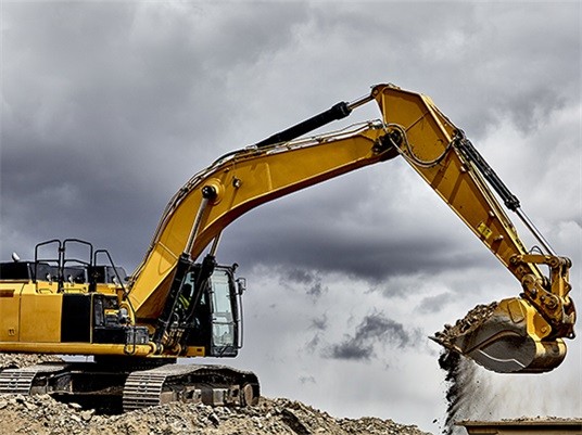
Excavator
Excavator

Deck crane
Deck crane
Please feel free to leave a message. We will reply you in 24 hours.

Submit Request
PDF Request
Simply fill out the form below and the catalog will be available for download!